Heating A ~2'x2' Aluminum Plate

Aluminum Bed Heated w/ Resistors
Why heat an aluminum plate? It's used to help the hot plastic coming out the 3d printer's nozzle to stick to the print bed (the aluminum plate with Kapton Tape on top of it). The plastic will warp/peel up if it's cooled too rapidly, and the heated plate helps it cool more slowly.

Why such a large plate? I'm making the machine for someone else, and they insist on making the printer huge. Print beds are usually a quarter of this size. I've had large prints on my smaller ~1'x1' printer warp/peel up even though they're on the heated bed, so I'm not sure if using the entire bed will be practical.

Why use aluminum? It's light, flat, and cost isn't a big issue for this project. It does act like a big heat sink though, so someday I would also like to try using just glass.

27 30 Ohm resistors wouldn't get the massive aluminum plate hot enough for PLA (60C) at 12V. So, I ended up getting a 15V power supply to get the heat to max out at only 65 degrees C. It was using 10.8 Amps at 12V with 27 resistors. Unfortunately, RepRap's RAMPS electronics can only handle 11A without blowing a fuse, so I wired the resistors directly to the new 15V power supply. It's doesn't need to be controlled by the RepRap's electronics because it consistently stays near the required 60 degrees C for PLA.

Here's info about the aluminum clad resistors I used (from Mouser):
71-RH10-30
RH01030R00FC02
10watts 30ohms 1%
Price: $2.83
Link: http://www.mouser.com/ProductDetail/Vishay/RH01030R00FC02/?qs=N4jMYmtGExdh5bRWPNF0Fg%3d%3d

Some things I learned:
  • It is going to take a lot more resistors/voltage/amps to heat such a large aluminum plate to 110 degrees C for ABS plastic. This setup should definitely work for a smaller ~12"x12" aluminum plate.
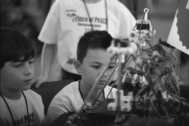
  • This definitely won't work if the resistors are in series, pay attention to how it's wired in the picture. (There's a wire going to one side of all the resistors, and another wire going to the other side of all the resistors.)
  • Amps per resistor go down as each resistor is added to the parallel circuit. More voltage makes the amperage through each resistor increase (Ohm's Law) and the heat will increase as the amperage through each resistor increases. The formula for resistance is (figure out the rest with Ohm's Law): 
    Rtotal = (R1−1 + R2−1 + …Rn−1)−1
  • Increasing the voltage past 12V was necessary, so a variable voltage power supply that can handle a large number of Amps would help here. I see them on Craigslist pretty consistently.
  • Adding insulation to the back really helped get it to heat past 60C (I just superglued cardboard over the resistors, maybe some kind of foam or wool would be better.)
  • JB Weld worked to glue the resistors to the plate, but some kind of thermal epoxy might have been better. Making a pool of JB weld, dipping the resistor, then putting it on the plate is the best way to do it.
  • Since the goal is generating heat, the resistors can be run over their watt rating.
  • 16 gauge "Heater Wire" from Ace Hardware works, but the Reprap IRC mentioned some type copper hardware to connect resistors like this more efficiently.
  • Using AC voltage may not be a bad idea, but it will require extra grounding and more danger. I attempted to use an AC to 18V DC transformer that plugged into the wall, but it couldn't handle all the current.
  • The resistance of the wire didn't seem to be enough to make a difference. I was worried about wiring all the resistors on the same path, because I thought less electricity would go through the last resistor.


O1 Tool Steel Rusts

For some reason, I was under the impression that O1 tool steel resisted rust. Leave it in the rain and it will rust magnificently.


Stepper Motor Comparison

I've been looking for stepper motors which are less expensive than the ones sold by Ultimachine and Lulzbot. So, I ordered some from China. I wanted to compare them with the steppers I got from Ultimachine, so I set up a testing rig:
Simple Rube Goldberg Machine?
Boring details: 
  • The green pulley has a 1 inch radius. 
  • In each of the tests, the motors are attached to the same stepper driver. This makes sure there is the same amount of current going to the motors in each of the tests.
  • I tried each test a few times, to make sure the results were consistent.
  • The motor is held to the table by a clamp.
  • I drilled a hole through the pulley, put the string through it, tied a knot, and wound the string around the pulley a few times. There is a nut on one end to hold it to the fish scale.
  • On the "moving torque" test, the fish scale was clamped down above the edge of the pulley and the motor pulled against it.
  • On the "holding torque" test, I just pulled the fish scale up until the motor skipped steps. 
  • Also, I recorded all the results from the scale with video and took a screenshot of the moment it hit maximum torque in each instance.


Chinese Motor Results (17hs8401):
Moving Torque: 12 oz-in

Holding Torque: 20 oz-in
After the tests, I attached it to my printer and printed a few things with it. It skipped a step near the first layer of the first print. However, I turned up the current a bit and it worked fine after that. It's a surprise this motor has more holding torque than the Kysan motor when the same amount of current is applied.

Kysan Motor Results (Ultimachine):
Moving Torque: 16 oz-in
Holding Torque - 16 oz-in
The Kysan motor has been on my printer for several months and it works well. It seems to have a stronger moving torque than the Chinese stepper when the same amount of current is applied.

Conclusion: Since I'm operating the motors at a 1/4th of their rated torque, it's no surprise that both motors work fine. To me this proves the Chinese motors aren't so crappy that they fail when operating at only 1/4th of their rated torque. 

Highly Calibrated

The Reprap IRC told me how to make "on the fly" changes to the calibration of my printer. This only works on Marlin Firmware for Reprap electronics though. An example of the process (if you wanted to change your steps per mm for the z axis to 2560): type M92 Z2560 in the pronterface console, M500 to save the changes, then M501 to view the changes. Now there's no longer any need to recompile the firmware just to tweak the calibration.

First thing I corrected was the Z steps per mm, but the even bigger difference came when I corrected the extruder's steps per mm again.

Here are the results:

Upgrade


The image on the left shows one of the mounts Lulzbot designed secure their acrylic electronics mount (my favorite electronics mount). The design has two screws which go through the acrylic plate and through the mount to be held in place by two nuts. It's one of those "Well, it works..." pieces. So, I redesigned it to use fewer (and shorter) screws and gave it a nut capture. The new mounts are the black things in the picture to the right.


The new design lives here: http://www.thingiverse.com/thing:18305

Showing Off


I got the chance to show off my Reprap at the North Texas Regional Lego League competition. An interesting question from a kid: "If you need another Reprap to print parts, how did they get the first set of parts?" I had to ask the Reprap IRC for the answer: A Wood Reprap


Credit: R. Steven Rainwater

New Thick Sheet Design

I hate having to drill my own holes in the Reprap's thick sheet because it's something that needs to be done with a good degree of planning and accuracy. So, I made a laser-cut design with holes for the LM8UU bushings, belt clamps, and heated bed.
Almost perfect, misaligned center holes.

First Design
http://www.thingiverse.com/thing:15888

Update 1: After testing it, some issues are starting to appear.
  • The placement of the belt clamp holes are incorrect, but they work (for me anyway). They need to be closer together so the belt clamp can move left/right. 
  • The LM8UU holes are larger than they need to be and they need to be about 15mm closer to the center of the plate. I'll be giving up about 30mm of print space on the Y axis until I move the LM8UU bushings closer to the center. 
  • It also wouldn't hurt if I moved each of the heated build plate holes out 1mm.

Cardboard is working well as an insulator between the heated bed and the mounting plate (I was surprised to hear it didn't conduct electricity. Perfect!).

Here's a picture of some mcguivered stand-offs for the heated build plate made from the corners of a broken fan:

Update 2: I attempted to fix the issues I described in Update 1, and now I still need to test it.
Second Design
Update 3: Moved the belt clamps, rounded the edges, and changed where the material was removed. It's currently on my machine now and it works!
Final Design